Introduction
A CAT 320 that feels sluggish on the stick, weak on the boom, or slow through a full cycle almost always traces back to one root cause: pump pressure that's out of spec. Every function — boom lift, swing torque, bucket crowd — depends on how precisely pressure and flow are set. The CAT 320 runs a tandem variable-displacement piston pump system where Pump 1 and Pump 2 must be independently calibrated to serve implement, travel, and swing circuits correctly.
Running outside specified pressure ranges accelerates wear on seals, valve plates, and piston assemblies. The damage is often silent — no warning until a major component fails under load.
This guide covers the factory pressure specs for both pumps, how to test and adjust them in the field, and what diagnostic steps to take when readings fall outside allowable tolerances.
Key Takeaways
- The CAT 320 runs a tandem variable-displacement axial piston pump (Part #589-1919) with independent flow and pressure regulation on Pump 1 and Pump 2
- Main relief pressure operates at 35,000 kPa (5,075 psi) in normal mode and 38,000 kPa (5,510 psi) in Heavy Lift/Auto Dig Boost mode
- Flow adjustment screws are highly sensitive — 1/4 turn shifts output by 19 L/min (5.0 US gpm)
- Locknut torque specs are 98 N·m for output flow and 177 N·m for max flow
- Operating outside spec accelerates seal wear, piston shoe damage, and valve plate scoring — often without triggering immediate visible symptoms
- When adjustment fails to restore specified pressure, suspect internal mechanical wear and get a professional evaluation
What Hydraulic Pump Pressure Represents in the CAT 320 System
Hydraulic pump pressure is the force per unit area generated by the piston pump to move hydraulic fluid through actuator circuits. It functions as both a design parameter—set by relief valves—and an operating variable influenced by load, temperature, and pump condition. In the CAT 320, pressure directly determines implement breakout force, lift capacity, swing speed, and travel power.
The CAT 320 employs a tandem variable-displacement axial piston pump (Caterpillar Part #589-1919). This system consists of two independently adjustable pumps—Pump 1 and Pump 2—operating in parallel. Combined output is directed to implement, travel, and swing circuits. The left joystick and left travel operate on one pump, while the right joystick and right travel operate on the other. Boom and stick circuits use special combiner arrangements to provide two-pump flow for faster operation.
Critical pressure distinctions:
- Main system pressure: Controlled by the main relief valve; governs maximum system-wide pressure
- Secondary/port relief pressure: Protects individual actuator circuits (travel, swing, implement lines)
- Pilot circuit pressure: Governs control valve responsiveness and joystick command sensitivity
These are not interchangeable specs. Each circuit has distinct pressure requirements and must be tested and adjusted independently.
Factors That Influence Pump Pressure in Real-World Operation
Published pressure specs assume standard operating temperature (55 ± 5°C), rated engine RPM (1860 ± 50 RPM no-load high idle), and fresh hydraulic fluid meeting CAT HYDO Advanced specifications. Because field conditions rarely match all three simultaneously, a reading that looks accurate under one test condition may fail under another — which is why understanding these variables matters before adjusting anything.
Load profile effects:
Sustained heavy digging or lifting drives pump pressure toward the relief threshold continuously, accelerating wear on piston shoes, valve plates, and barrel bores. This differs from intermittent loading — component life shortens even when pressures stay within spec.
Fluid viscosity and temperature:
- Cold starts: Thick hydraulic fluid increases internal friction and reduces volumetric efficiency, producing falsely low pressure readings during initial operation
- Overheated systems: Thinned fluid reduces internal sealing, increases slip flow, and lowers achievable pressure under load
- Contaminated fluid: Dirt and particulate accelerate valve plate scoring and piston shoe wear, causing volumetric efficiency loss that mimics low-pressure symptoms
CAT 320 Hydraulic Pump Pressure Specs and Operating Ranges
The CAT 320 hydraulic system is governed by several pressure references, each serving a distinct circuit protection or control function. All specs below are sourced from CAT 320 technical documentation and must be verified at the correct test conditions: hydraulic oil at 55 ± 5°C (131 ± 9°F), engine speed dial at position "10" (1860 ± 50 RPM no-load high idle), and the opposite pump unloaded.
Nominal Operating Range
Main Relief Valve Pressure:
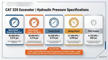
- Normal mode: 35,000 kPa (5,075 psi)
- Heavy Lift/Auto Dig Boost mode: 38,000 kPa (5,510 psi)
The system should maintain a 1,000 kPa (145 psi) differential between heavy lift and standard lift modes. Technicians must verify pressures in both modes using the heavy lift switch to ensure the differential is maintained. Failure to test both modes can result in under-performance during critical lifts.
Travel Circuit Relief Pressure: 34,300 kPa (4,974 psi)
Swing Circuit Relief Pressure: 27,500 kPa (3,998 psi)
Pilot System Maximum Pressure: 4,120 kPa (600 psi); during testing, verify pilot relief valve setting at 4,100 ± 200 kPa (595 ± 29 psi)
Pump 1 and Pump 2 have identical nominal specs but must be tested and adjusted independently. A significant difference in output between the two pumps indicates a calibration error or internal wear issue.
Allowable Tolerance and Boundary Limits
Knowing the nominal specs is only half the job — calibration requires understanding how far each circuit can deviate before it falls outside specification. Caterpillar defines target set values and allowable measured deviations for each pressure circuit:
- Main relief valve: Target 35,000 kPa; CAT does not publish an explicit tolerance; field practice typically accepts ±500 kPa (±72 psi)
- Pilot relief valve: Target 4,100 kPa; allowable range 4,100 ± 200 kPa (595 ± 29 psi)
Continuous operating pressure describes the range the system maintains during normal work cycles — below the relief ceiling and within the pump's efficient output band. Peak/relief pressure is where the relief valve opens to cap system pressure.
Running continuously at or near relief pressure is a design boundary condition, not a normal operating state. Sustained operation at that ceiling wastes energy as heat and accelerates relief valve seat wear.
Safe Operating Margin
CAT engineers build margin between maximum working pressure and the relief valve opening point to handle real-world shock loads. A bucket striking hard ground or a sudden travel direction reversal can spike system pressure well above the steady-state working range — that margin absorbs the spike rather than forcing the relief valve open on every impact.
The practical benefits of maintaining that margin:
- Limits transient pressure spikes from sudden load changes
- Prevents the heat buildup that comes from repeated relief valve bypassing
- Extends seal and piston shoe service life by reducing peak stress frequency
Caterpillar documentation does not explicitly define the designed safety margin between continuous working pressure and relief ceiling for the CAT 320. Operators and technicians must strictly enforce the 35,000/38,000 kPa hard ceilings rather than relying on assumed engineering safety factors.
How to Adjust the CAT 320 Hydraulic Pump: Flow and Pressure Procedures
Each adjustment procedure below requires the system to be in a controlled baseline state. Before starting, confirm all of the following:
- Engine RPM at spec: speed dial at position "10," AEC switch OFF, 1860 ± 50 RPM no-load high idle
- Hydraulic fluid at operating temperature: 55 ± 5°C (131 ± 9°F)—achieved by moving the stick through full travel several times
- Opposite pump unloaded: when testing Pump 1, Pump 2 must remain at low-pressure standby, and vice versa
- System air purged: slow output flow indicates air in the hydraulic system; purge before adjustment
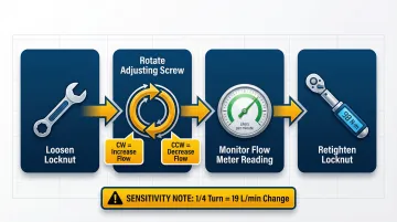
Flow Control Adjustment (Output Flow Screw)
- Loosen the locknut on the output flow adjustment screw
- Rotate the adjusting screw:
- Clockwise increases output flow
- Counterclockwise decreases output flow
- Monitor flow using a calibrated flow meter at the test port
- Retighten the locknut to 98 ± 9.8 N·m (70 ± 7 lb ft)
Each 1/4 turn changes output flow by approximately 19 L/min (5.0 US gpm) in the pressure range of 11,800 kPa (1,700 psi) to 19,600 kPa (2,850 psi). Make small adjustments and retighten the locknut promptly to maintain calibrated flow settings.
Maximum Output Flow Adjustment
- Loosen the locknut on the maximum output flow adjustment screw
- Rotate the adjusting screw:
- Clockwise decreases maximum output flow
- Counterclockwise increases maximum output flow
- Monitor flow using a calibrated flow meter
- Retighten the locknut to 177 ± 15 N·m (130 ± 11 lb ft)
Each 1/4 turn changes maximum output flow by approximately 5 L/min (1.3 US gpm). This screw functions in the opposite rotational direction from the output flow screw.
Pressure Relief Valve Adjustment
The main relief valve is located on top of the main control valve, not the pump regulator.
- Connect a calibrated pressure gauge (49,000 kPa or 60,000 kPa range) to the designated test port
- Loosen the locknut on the main relief valve adjustment screw
- Rotate the adjusting screw:
- Clockwise increases pressure
- Counterclockwise decreases pressure
- Monitor the gauge until the specified pressure is reached
- Always make final pressure adjustments on pressure rise (approach target from below)
- Retighten the locknut to 50 ± 10 N·m (37 ± 7 lb ft)
Temporary main relief override for line/port relief testing:
Because line relief valve pressure settings (36,800 kPa) are higher than the main relief valve setting (35,000 kPa), the main relief valve must be temporarily adjusted higher before testing line relief valves. Loosen the locknut and turn the adjustment screw clockwise for one-half turn. After adjusting line relief valves, the main relief pressure must be returned to its normal setting and verified with a gauge.
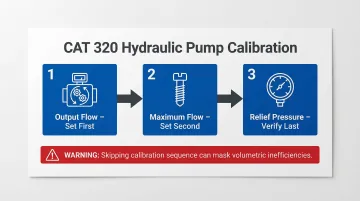
Adjustment Sequence
Critical: Adjustments must be performed in the correct sequence:
- Output flow (set first)
- Maximum flow (set second)
- Relief pressure (verify last)
Skipping this sequence can mask volumetric inefficiencies — a system may pass one check while failing another, resulting in erratic implement speeds.
How to Measure and Verify CAT 320 Hydraulic Pressure
Specification and Test Port Reference
Pressure test ports are located in the pump compartment:
- Tap (1): Power shift pressure
- Tap (2): Front pump (right pump delivery pressure)
- Tap (3): Rear pump (left pump delivery pressure)
These port locations are documented in the CAT 320 service manual (SENR6466 or applicable version). Use correct port adapters and pressure gauge fittings to avoid leaks and false readings.
Instrumentation Requirements
Gauge range requirements:
- Main relief and line relief valves: 49,000 kPa (7,100 psi) or 60,000 kPa (8,700 psi) pressure gauge
- Power shift and pilot pressures: 4,900 kPa (700 psi) or 6,000 kPa (870 psi) pressure gauge
Use calibrated digital hydraulic pressure gauges or analog gauges with appropriate psi/kPa range for each circuit. Zero and calibrate the gauge before measurement to avoid false readings. The Cat Hydraulic System Test Tool Kit (Part #456-6429) includes gauges, fittings, hoses, and adapters necessary for diagnostic testing.
Field vs. Lab Measurement Differences
Field measurements should be taken under the following conditions:
- Machine on level ground
- Hydraulic oil at normal operating temperature: 55 ± 5°C (131 ± 9°F)
- Engine at rated RPM: 1860 ± 50 RPM no-load high idle
- Opposite pump unloaded
Any deviation — cold oil, incorrect RPM, or simultaneous loading of both pumps — produces readings that don't reflect true system performance and should not drive adjustment decisions.
What Happens When CAT 320 Hydraulic Pressure Is Out of Spec
Performance Loss Mechanisms
Low main relief pressure:
- Weak implement force and inability to complete rated lift capacity
- Slow cycle times across all functions
- Reduced breakout force at the bucket and stick
High relief pressure:
- Increased heat generation, raising fluid temperature and reducing viscosity
- Accelerated seal wear due to sustained high-pressure stress
- Relief valve seat damage over time from continuous bypassing
- Energy waste and reduced fuel efficiency
Hydraulic system failures account for 47% of total maintenance spend in excavator fleets, averaging $38,000 per incident across pump replacements, cylinder rebuilds, and hose failures. Those costs trace directly to the mechanical wear patterns that out-of-spec pressure creates.
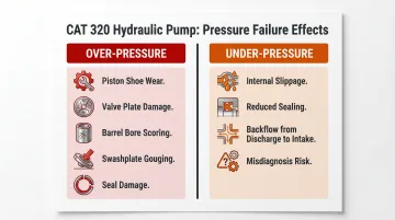
Accelerated Wear and Failure Modes
Sustained over-pressure:
- Stresses piston shoes, causing rounded edges, loose fit on the ball, and excessive wear on the backs of the shoes
- Damages valve plate faces through increased contact force and heat
- Scores barrel bores, reducing volumetric efficiency
- Causes half-moon gouging or full-moon scoring of the swashplate
- Damages shoe retainers, bends seal retainers, and causes shaft seals to protrude
Sustained under-pressure:
- Allows internal slippage, increasing volumetric inefficiency
- Reduces sealing effectiveness between piston and barrel
- Permits backflow from discharge chamber to intake chamber, wasting energy
- Technicians often misdiagnose this as an engine or control valve issue before inspecting the pump
Both conditions accelerate component wear and often do not trigger visible symptoms immediately. Operators may notice gradual performance degradation over weeks or months before catastrophic failure occurs.
When Adjustment Is Not Enough: Recognizing Internal Pump Wear
If pressure cannot be brought within spec through adjustment, or if adjusted values drift rapidly (within hours or days), internal wear is likely the root cause. Common internal wear conditions include:
- Scored barrel bore — fluid slips past the piston, dropping volumetric efficiency
- Worn piston shoes — fluid leaks at the swashplate interface, reducing output pressure
- Damaged valve plate — flow timing breaks down, making consistent pressure regulation impossible
When these conditions are present, adjusting relief settings treats the symptom while the underlying failure continues. Hydrostatic Pump Repair evaluates, rebuilds, and sources replacement components for CAT 320 pump assemblies when adjustment procedures fail to restore spec. Call 1-800-361-0028 to discuss diagnostic evaluation and rebuild options.
Frequently Asked Questions
What is the normal hydraulic operating pressure on a CAT 320 excavator?
The main system operating pressure is 35,000 kPa (5,075 psi) in normal mode and 38,000 kPa (5,510 psi) in Heavy Lift/Auto Dig Boost mode. Pilot circuit pressure operates at 4,120 kPa (600 psi), and travel/swing circuits have separate relief pressures of 34,300 kPa and 27,500 kPa, respectively.
How much hydraulic fluid does a CAT 320 hold?
The CAT 320 hydraulic system has a total refill capacity of 234 L to 240 L (61.8 to 63.4 gal), with the hydraulic tank holding 115 L to 128 L (30.4 to 33.8 gal). Caterpillar recommends Cat HYDO Advanced 10, 20, or 30 hydraulic oil depending on ambient temperature.
What happens if the CAT 320 hydraulic pump pressure is set too high?
Over-pressure accelerates seal and valve plate wear, increases heat rejection load on the cooler, and risks relief valve seat damage. Symptoms include excessive heat, rapid fluid degradation, and reduced component service life.
How do I know if my CAT 320 hydraulic pump needs adjustment or replacement?
If pressure readings fall outside spec and won't stabilize after adjustment, or if output flow keeps dropping despite correct settings, internal mechanical wear is the likely cause. Rapid drift of adjusted values within hours or days points to scored barrels, worn piston shoes, or damaged valve plates — all warranting pump inspection or rebuild.
What tools are needed to adjust the CAT 320 hydraulic pump pressure?
Essential tools include a calibrated hydraulic pressure gauge (49,000 kPa range for main relief, 4,900 kPa range for pilot) with correct port fittings, a torque wrench covering 50 N·m, 98 N·m, and 177 N·m ranges, and the appropriate hex/Allen key for adjustment screws. Access to the CAT service manual is required for test port locations and target values.
What is the correct torque spec for the CAT 320 hydraulic pump adjustment locknut?
The flow control adjusting screw locknut requires 98 ± 9.8 N·m (70 ± 7 lb ft), and the maximum output flow locknut requires 177 ± 15 N·m (130 ± 11 lb ft). The main relief valve locknut requires 50 ± 10 N·m (37 ± 7 lb ft). All locknuts must be retorqued after every adjustment to prevent setting drift.