Introduction
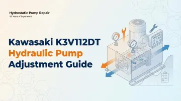
The Kawasaki K3V112DT is a variable displacement axial piston pump widely used in excavators, cranes, and other mobile heavy equipment. Its swash plate design delivers reliable hydraulic power in 20–30 ton class machines like the Kobelco SK200/SK210 and Daewoo DH215-9. Without proper adjustment and maintenance, performance degrades fast.
Neglected pumps show reduced hydraulic flow, pressure loss, internal leakage, and accelerated wear on the servo piston, swash plate, and other internal components. When contamination or wear goes unchecked, inefficiencies compound into major failures.
This guide covers:
- Key pump components and how they work together
- Warning signs that indicate adjustment is needed
- Step-by-step adjustment methods
- Routine maintenance tasks
- A recommended service schedule to maximize pump life
Key Takeaways
- The K3V112DT uses regulator lock nuts and adjustment screws to control output flow and pressure
- Slow operation at low or high pressure signals the need for adjustment
- Flow adjustments use the regulator lock nut and adjustment nut, turned in 1/4-turn increments
- Pressure adjustments use the small lock nut and square adjusting screw, also in 1/4-turn increments
- Routine maintenance (fluid checks, filter replacement, seal inspection, temperature monitoring) prevents costly failures
- When adjustment cannot restore performance, professional pump repair or parts replacement is required
Understanding the Kawasaki K3V112DT: Key Components and How It Works
The K3V112DT is a swash plate variable displacement pump with over 25 years of proven use in mobile hydraulic applications. The "DT" designation indicates a tandem (double pump) configuration, with front and rear pump sections sharing a common drive shaft. It offers high power density and a wide range of control options.
| Specification | Value |
|---|---|
| Rated pressure | 34.3 MPa |
| Peak pressure | 39.2 MPa |
| Displacement | 112 cm³/rev |
Operating Principle: The drive shaft rotates the cylinder block, causing pistons to stroke in and out to draw and discharge hydraulic oil. Output flow and pressure are controlled by changing the swash plate angle via the servo piston. This variable displacement design makes adjustment possible without disassembly—a critical advantage for field service.
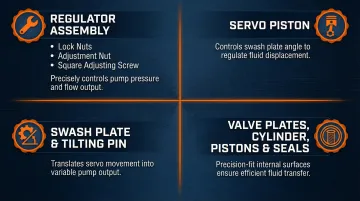
Knowing which components handle each function makes field adjustments faster and safer. Here are the four areas you'll interact with most:
- Lock nuts, adjustment nut, and square adjusting screw form the regulator assembly — your primary interface for setting flow and pressure without disassembly
- The servo piston shifts the swash plate angle in response to system pressure, directly controlling displacement
- The swash plate support and tilting pin translate servo movement into actual output change
- Valve plates, cylinder, pistons, and seals are precision-fit surfaces — keep them clean, as contamination is the leading cause of premature wear
Signs Your K3V112DT Pump Needs Adjustment or Maintenance
Before adjusting or servicing the pump, identify the specific symptom you're experiencing. Each symptom points to a different adjustment or maintenance action.
Sluggish or Slow Machine Operation
Low-pressure slow operation: Slow movement during light loads, boom lowering, or swing functions typically indicates the low-pressure regulator setting has drifted. Correct this by adjusting nut ② inward.
High-pressure slow operation: Slow movement specifically during heavy lifts or digging under load points to the high-pressure setting. Adjust the square adjusting screw ④ inward.
Excavator or Equipment "Holding" at Pressure (Won't Release Smoothly)
Actuators that stall, hesitate, or fail to release smoothly when transitioning between load states indicate the regulator is set too tight — the pump holds pressure rather than reducing displacement.
Corrective actions:
- Low-pressure holding: Adjust nut ② outward in 1/4-turn increments
- High-pressure holding: Adjust screw ④ outward in 1/4-turn increments
Reduced Overall Flow or Power Loss
General reduced machine performance — slower cycle times across all functions, engine loading under normal conditions — typically traces to one of three causes:
- Incorrect maximum or minimum flow settings on the regulator
- Contaminated hydraulic fluid
- Worn internal components
Visible Leaks, Noise, or Unusual Vibration
External leaks around the seal cover, drain port, or valve block signal seal wear or loose connections and require maintenance rather than regulator adjustment. Excessive noise or vibration points to a different set of problems:
- Bearing wear or fatigue
- Cavitation from restricted inlet flow
- Oil contamination affecting fluid film integrity
Contamination deserves particular attention: Parker Hannifin's Handbook of Hydraulic Filtration reports that over 75% of hydraulic system failures stem directly from contamination. Particulate contaminants degrade internal surfaces through abrasion, widening clearances and dropping volumetric efficiency over time.
Internal leakage (reduced volumetric efficiency with no visible external leak) often presents as pressure that cannot be sustained under load and requires disassembly inspection — external adjustment won't resolve it.
Kawasaki K3V112DT Hydraulic Pump Adjustment Methods
The K3V112DT uses four primary adjustment points: maximum flow, minimum flow, low-pressure regulation, and high-pressure regulation. Each requires a specific sequence and strict limits to avoid recalibration.
Safety first: Always relieve system pressure before touching the regulator. Use the correct tools, make incremental adjustments of no more than 1/4 turn per step, and never exceed 2 full turns total on any single adjustment screw. Only personnel familiar with hydraulic systems should perform these adjustments. When uncertain, contact a certified hydraulic technician.
Maximum Flow Adjustment
This controls the upper displacement limit of the pump.
- Loosen the regulator lock nut
- Turn the adjustment screw clockwise to increase maximum flow, counterclockwise to decrease it
- Stay within the 2-turn total limit across all adjustments
- Re-tighten the lock nut and test operation after each 1/4-turn increment
Minimum Flow Adjustment
Note the reversed screw logic here compared to maximum flow adjustment.
- Loosen the regulator lock nut
- Turn the adjustment screw clockwise to decrease minimum flow, counterclockwise to increase it
- Stay within the 2-turn total limit
- Monitor engine response during adjustment, then re-tighten the lock nut securely
Low-Pressure and High-Pressure Regulator Adjustment
Use this four-scenario reference to match symptoms to the correct adjustment:
| Symptom | Lock Nut | Adjustment | Direction |
|---|---|---|---|
| Low pressure slow | Large lock nut ① | Nut ② | Inward 1/4 turn |
| High pressure slow | Small lock nut ③ | Screw ④ | Inward 1/4 turn |
| Holding at low pressure | Large lock nut ① | Nut ② | Outward 1/4 turn |
| Holding at high pressure | Small lock nut ③ | Screw ④ | Outward 1/4 turn |
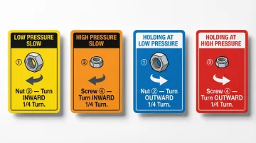
Retighten the relevant lock nut after each increment before re-testing.
Variable Displacement and Alignment Checks
The servo piston and tilting pin assembly control displacement on the K3V112DT. Never loosen the stroke adjustment nuts on the valve block or swash plate support during field adjustment — doing so permanently alters the calibrated flow setting and requires professional re-calibration.
After any adjustment, verify coupling alignment:
- Check pump-to-engine coupling alignment after any regulator change
- Inspect again following high-hour operation
- Misalignment accelerates bearing and seal wear, and can nullify correct regulator settings
Essential Maintenance Practices for the K3V112DT
Even correctly adjusted pumps will fail prematurely without consistent maintenance of the hydraulic fluid, filters, and seals. This section provides the preventive layer that makes adjustments last.
Hydraulic Fluid and Filter Maintenance
Check hydraulic fluid level at every daily pre-shift inspection. Filter replacement intervals vary by machine — for reference:
- Komatsu PC210-7 specifies a 1,000-hour interval for the hydraulic oil filter
- Volvo EC220 specifies a 2,000-hour interval for the hydraulic oil return filter
- Kawasaki KPM recommends a nominal 10 µm filter in the return line
Use only the fluid viscosity grade specified for your application temperature range to avoid cavitation or excessive wear.
Contaminated oil is the leading cause of K3V112DT internal component failure. Particles in the oil accelerate wear on pistons, shoes, swash plate, and valve plates. Flush the system after any major repair to remove debris before returning the pump to service.
Seal and Leak Inspection
Inspect the following at regular intervals for weeping or wet residue:
- Seal cover (front and rear)
- Drain port plugs
- O-rings on the valve block
- All hydraulic line connections
Replace any compromised seal immediately using the correct O-ring specifications for the K3V112DT. Hydrostatic Pump Repair stocks seal components and replacement parts for the K3V series, including items that are difficult to source through standard channels.
Temperature and Bearing Monitoring
Install a temperature gauge on the hydraulic tank return line. Bosch Rexroth states that tank temperatures exceeding 80°C (176°F) halve service life for every 10°C of additional increase.
Watch for these bearing wear indicators:
- Unusual whining, grinding, or rhythmic noise at the pump shaft
- Increased vibration at the mounting flange
- Detectable play at the drive shaft
Any of these symptoms call for a bearing inspection — on the roller bearing and needle bearing specifically. Do not attempt to compensate with regulator adjustment.
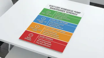
K3V112DT Maintenance and Adjustment Schedule
Interval recommendations vary based on operating hours, load intensity, and environmental conditions. Dusty or hot environments require more frequent checks. Always defer to the equipment OEM's service manual for model-specific intervals.
Maintenance Frequency Reference:
| Interval | Tasks |
|---|---|
| Daily / Pre-shift | Hydraulic fluid level check; visual leak inspection around seal covers and hose connections; check for unusual noise or vibration during startup |
| Every 250–500 hours | Hydraulic filter replacement; seal condition inspection; check regulator adjustment nuts for looseness from vibration |
| Every 1,000–2,000 hours | Full fluid change; bearing condition assessment; valve plate and swash plate inspection (if performance has degraded); alignment verification |
| Major overhaul or after pump failure | Full disassembly per repair manual sequence; replace all seals and O-rings; inspect and replace pistons/shoes/cylinder if worn; re-calibrate flow settings with professional equipment |
Usage Intensity Notes:
- High-cycle continuous operation (multi-shift excavators): Compress all intervals by at least 30%
- Severe duty (hydraulic hammer usage): Caterpillar mandates that if a hydraulic hammer is used 100% of the time, the hydraulic system oil change interval is reduced to 600 service hours
- Intermittent or light-duty operation: Extended intervals may apply — but daily visual checks are non-negotiable regardless of hours logged
Conclusion
The Kawasaki K3V112DT is a precision hydraulic component. Incremental regulator adjustments — no more than 1/4 turn at a time, within the 2-turn limit — combined with consistent preventive maintenance are what keep these pumps running for thousands of hours rather than failing ahead of schedule.
Not all symptoms can be resolved through external adjustment. When performance issues persist after correct regulator procedures, when internal leakage is suspected, or when noise and bearing wear are detected, the pump needs professional inspection — not more adjustment.
Hydrostatic Pump Repair specializes in K3V series rebuild and repair. Call 800-361-0028 to discuss your pump's symptoms and get it back to spec.
Frequently Asked Questions
What is the Kawasaki K3V112DT hydraulic pump used for?
The K3V112DT is a variable displacement axial piston pump primarily used in hydraulic excavators and mobile cranes. It serves as the main pump supplying flow to the drive motors, boom, arm, and bucket cylinders in 20–30 ton class excavators.
How do I adjust the maximum flow on a Kawasaki K3V112DT?
Loosen the regulator lock nut and turn the adjustment screw clockwise to increase flow, or counterclockwise to decrease it. Work in increments no greater than 1/4 turn, with a maximum of 2 full turns total.
What causes a Kawasaki K3V112DT pump to lose pressure under load?
Common causes include the high-pressure regulator set too low, worn seals causing internal leakage, contaminated hydraulic fluid degrading volumetric efficiency, or worn pistons and valve plates requiring internal inspection.
How often should I service a Kawasaki K3V112DT hydraulic pump?
Daily visual checks are essential. Filter changes should occur at 250–500 hour intervals and full fluid changes at 1,000–2,000 hours. Severe-duty or high-intensity applications may require filter service as frequently as every 600 hours.
What happens if your hydraulic pump is too big?
An oversized pump delivers more flow than the system requires, forcing excess flow through relief valves and converting wasted horsepower into heat. This causes accelerated component wear and makes precise pressure and flow control difficult to achieve.
When should I replace rather than adjust my K3V112DT pump?
Consider replacement or a professional rebuild when regulator adjustments fail to restore performance, or when internal inspection reveals worn pistons, cylinder bores, or valve plates. Persistent noise and bearing damage are clear signs the rotary group has reached the end of its service life.