Introduction
Rebuilding a Cornell centrifugal pump is a technically demanding process that requires mechanical competence, model-specific precision, and strict adherence to Cornell's clearance and torque specifications. This is not a task for untrained personnel. Improper assembly can trigger cascading mechanical failures that cost far more than the original repair.
Only experienced pump mechanics, trained maintenance technicians, or pump shop professionals familiar with centrifugal pump assembly should attempt a Cornell pump rebuild. Without the right tools and Cornell's published specifications, a well-intentioned rebuild can compound the original failure.
The consequences of incorrect assembly are specific and serious:
- Premature bearing failure from over-greasing or improper seating
- Mechanical seal leaks caused by contaminated faces or incorrect installation
- Cavitation from impeller clearances set outside Cornell's tolerances
- Unplanned downtime averaging $260,000 per hour in U.S. manufacturing
Key Takeaways
- Cornell rebuilds follow a fixed sequence: disassembly, inspection, seal/bearing replacement, impeller shimming, and frame reassembly
- Backvane, wear ring, and bearing frame clearances are model-specific — always verify against your pump's data sheet
- Frame lubrication type (grease vs. oil) must match the frame; over-greasing causes 33% of bearing failures
- The 7 PSI air test on run-dry cavities is mandatory before returning to service
- If critical clearances cannot be achieved, escalate to a qualified pump service provider
Before You Begin: Prerequisites, Safety, and Tools
Prerequisites and Safety Considerations
Identify the exact pump model and frame size from the serial number plate before sourcing parts or beginning disassembly. Clearance tables, shim specifications, and lubrication requirements vary by frame and model, so this step is non-negotiable.
Safety protocols:
- De-energize and lock out the pump drive system completely
- Drain all process fluids from the casing
- Ensure adequate workspace with lifting equipment for larger frames
- Do not proceed without Cornell service documentation (clearance charts, torque tables)
Confirm all replacement parts are sourced to the correct specification before disassembly begins:
- Mechanical seal (model-specific)
- Bearings (frame-specific)
- Wear rings (clearance-matched to model)
- Impeller lockscrew (correct thread size)
- O-rings and gaskets (material-compatible)
Suppliers with access to Cornell-compatible parts inventories, such as Hydrostatic Pump Repair, can help locate hard-to-find components for specific frame sizes. Once parts are confirmed, gather the tools and consumables the job requires before touching the pump.
Tools and Parts Required
Essential tools for Cornell pump rebuilds:
- Dial indicator (for end play and shim gap measurement)
- Depth gauge and feeler gauge
- Frame-specific Cornell press plates (F16, F18, F20)
- Impeller puller and threaded removal wrench
- Packing installation tools
- Hand-operated grease gun
- Fast-drying cleaning fluid (leaves no residue)
Specialized Cornell tools:
- F16/18 assembly stand
- SAE spline-to-shaft adapters
- Source these through Cornell distributors. Do not improvise substitutes; improper tooling can damage bearing seats or shaft threads.
Required consumables:
| Consumable | Specification | Application |
|---|---|---|
| Grease | Mobil Mobilux EP2 or Shell Gadus S2 V220 2 (NLGI Grade 2) | Grease-lubricated frames |
| Turbine Oil | ISO VG32 (oil temp <150°F) or VG68 (>150°F) | Oil-lubricated frames |
| Threadlocker | Loctite 262 or equivalent | Impeller lockscrew |
| Anti-seize | High-temperature lubricant | Threaded impeller installation |
| Propylene Glycol | Industrial grade | Run-dry cavity refill |
How to Rebuild a Cornell Pump: Step-by-Step Assembly Instructions
A Cornell pump rebuild follows a defined sequence: disassembly and inspection, component replacement, impeller installation and shimming, frame assembly, and final alignment checks. Skipping or reversing steps (particularly installing the impeller before achieving correct clearances) is a leading cause of rebuild failures.
Disassembly and Initial Inspection
Remove the pump casing and document component positions before removal. Note the frame size from the serial number plate. Photograph backvane and wear ring positions before disassembly to serve as reassembly reference.
Inspection checklist:
- Check shaft for runout (must be concentric within 0.002" TIR)
- Examine bearing seats for fretting or corrosion
- Assess wear ring clearances against model-specific replacement thresholds
- Identify whether mechanical seal failure was primary or caused by shaft misalignment or contaminated seal faces
Replacing Bearings, Seals, and Wear Components
Install the new mechanical seal using the correct Cornell procedure for the seal type. For pumps with a run-dry cavity:
- Connect the air test apparatus after seal installation
- Pressurize to exactly 7 PSI (not more—excess pressure damages the seal)
- Close the valve and disconnect the air hose
- Allow to sit 5 minutes and rotate the shaft by hand
- Any pressure drop indicates a leak that must be resolved before continuing
For bearing replacement:
- Use the appropriate frame-specific press plate to avoid damaging bearing bores
- Never use impact tools on bearing races
- On oil-lubricated frames, lubricate lip seals in bearing covers through the grease fittings at either end of the frame
Impeller Installation and Shimming
For threaded impellers:
- Clean all threads thoroughly with solvent or brake cleaner
- Apply anti-seize lubricant to shaft and impeller threads
- Use a crane or support to align the impeller perpendicular to the shaft—do not spin the impeller onto the shaft
- Rotate the shaft by hand to thread the impeller on, having a second person assist to prevent cross-threading
Backvane clearance shims:
Standard backvane clearance is 0.030" ± 0.008" for most models, with exceptions:
- 4HM: 0.055"
- 3HC: 0.085"
Measure the distance from sleeve or thrust washer face to backplate surface and compare to impeller hub measurement. Once tightened, clearance will reduce by 0.010"–0.015", so account for this when selecting shim pack.
With shimming complete and impeller clearances confirmed, the frame is ready for final assembly and lubrication.
Frame Assembly and Lubrication
For grease-lubricated frames:
- Use only a hand-operated grease gun
- Pump a small amount into each bearing cavity — excess grease shortens bearing life by causing heat buildup and seal damage
- Frame 16/18 regreasing intervals: every 1,500 hours for 8-hour service, 9 weeks for 24-hour service
For oil-lubricated frames:
- Fill to the indicated level using the correct turbine oil grade
- ISO VG32 for oil temperatures below 150°F
- ISO VG68 for temperatures over 150°F
- Check oil level only when the pump is not running
- Oil renewal intervals: 3–4 months for smaller frames, 5–6 months for larger frames
Critical Clearances and Torque Specifications
Getting clearances and torque values right is where rebuilds succeed or fail. Bearing frame clearances must be verified using a dial indicator after shimming. For F16/F18 frames, correct shaft end play is .007"–.012" (F16X: .005"–.010").
F16/F18 Shim Selection Table:
| Measured Shim Gap | Required Shim Size |
|---|---|
| .002" to <.007" | None |
| .007" to <.012" | 0.005" |
| .012" to <.017" | 0.010" |
| .017" to <.022" | 0.015" |
| .022" to <.027" | 0.020" |
Measure by pushing the shaft to the pump end, zeroing the indicator on the bearing outer race, then measuring at the bearing cover.
Wear ring clearances are model-specific. Replace wear rings when clearance reaches the published replacement threshold — for many 3–6" clear liquid models, that's .067"–.072". Oversized wear ring clearances can increase axial thrust by 203% and cause efficiency loss and vibration.
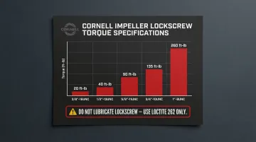
Impeller Lockscrew Torque Specifications:
Cornell requires significantly lower torque values than standard engineering references when using Loctite 262. Do not lubricate the lockscrew or tapped hole.
| Thread Size | Cornell Specified Torque |
|---|---|
| 3/8"-16UNC | 20 ft-lb |
| 1/2"-13UNC | 40 ft-lb |
| 5/8"-11UNC | 90 ft-lb |
| 3/4"-10UNC | 135 ft-lb |
| 1"-8UNC | 260 ft-lb |
After all internal components are assembled and torqued, hand-rotate the shaft to confirm it spins freely — no binding, grinding, or resistance — before closing the casing.
Post-Rebuild Testing and Validation
Before commissioning, run the air pressure test: pressurize to 7 PSI, hold for 5 minutes, and rotate the shaft by hand. If pressure holds, release and proceed to installation.
If pressure drops, spray soapy water around the shaft and lip seal area to locate the leak. No external leak visible? Remove and inspect the mechanical seal faces and O-rings for nicks, tears, or contamination, then retest.
Initial run checks after reinstallation:
- Observe pump discharge pressure against expected shut-off pressure
- Listen for abnormal noise (cavitation sounds like gravel; bearing noise presents as a high-pitched whine)
- Check for visible leaks at the seal gland, casing joints, and pipe connections
Document the rebuild:
- Record shim pack sizes installed
- Note bearing part numbers
- Document oil or grease type used
- Record wear ring clearances measured
- Include date of rebuild
A complete rebuild log lets you cross-reference part wear against operating hours, support any warranty claims, and set a realistic service interval for the next inspection.
Common Cornell Pump Rebuild Problems and Fixes
Mechanical Seal Leaking After Rebuild
Problem: Seal gland leaks immediately or within the first hours of operation after rebuild.
Common causes include seal faces contaminated with grease or solvent during installation, a displaced O-ring, or a seal that wasn't seated squarely in the bracket face. The bracket face must be square with the shaft within 0.004" TIR.
Fix: Disassemble and clean all seal surfaces with fast-drying cleaning fluid. Inspect O-rings for nicks, reinstall with clean dry hands, confirm correct orientation and square seating, then repeat the air test before returning to service.
Bearing Overheating or Premature Failure
Problem: Bearing frame runs hot or bearings fail shortly after rebuild.
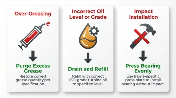
The three most common causes:
- Over-greasing — surplus grease churns and generates heat
- Incorrect oil level or wrong grade — especially mismatched ISO-grade turbine oil
- Impact installation — bearing driven against the inner race rather than pressed evenly
Fix: For grease frames, purge excess grease and restore the correct regreasing quantity per the frame-size table. For oil frames, drain and refill to the correct level with the appropriate ISO-grade turbine oil. If bearings show fretting damage on the outer race, check shaft endplay against the published specification and adjust the shim pack accordingly.
Low Pressure or Reduced Flow After Rebuild
Problem: Pump fails to meet design pressure or flow after reassembly.
The likely culprits: impeller backvane clearance set too large (which increases bypass flow), wear ring clearance past the replacement threshold, or incorrect impeller-to-casing vane clearance on open-vane models.
Fix:
- Measure actual backvane clearance with a feeler gauge and compare to the model-specific value in Cornell's critical clearance chart.
- Adjust the shim pack if the reading falls outside tolerance.
- Check wear ring clearances against the published standard and replace any rings at or beyond the replacement threshold.
Frequently Asked Questions
Is it worth rebuilding a water pump?
Rebuilding is cost-effective for quality pumps like Cornell models, especially when the frame and volute are undamaged. Rebuilding typically costs significantly less than full replacement and restores original performance when done correctly.
How much does it cost to rebuild a Cornell pump?
Rebuild costs vary based on pump size, frame type, and extent of wear. For industrial centrifugal pumps, rebuilds generally range from $500–$3,000 depending on frame size, with larger municipal pumps potentially costing more.
What is the warranty on Cornell pumps?
Cornell offers a 12-month warranty on most pump types (refrigeration, irrigation, food/hot oil, industrial, municipal) from date of shipment. Wear parts such as seals, wear rings, and wear plates are excluded unless a manufacturing defect is identified.
How long do mechanical seals last on pumps?
Mechanical seal lifespan depends on the pumped fluid, operating conditions, and maintenance quality. Seals typically last 2–5 years in clean water service, but seals running dry even briefly suffer accelerated wear—damage begins within 5 to 10 seconds of dry operation.
Where are Cornell pumps made?
Cornell Pump Company is headquartered in Clackamas, Oregon, USA, and has been manufacturing centrifugal pumps since 1946. The company was founded by five former Pacific Pump Company employees and continues to manufacture pumps domestically.
What are the most common reasons a Cornell pump needs rebuilding?
The primary causes are mechanical seal failure from dry running or contamination, bearing failure from improper lubrication or over-greasing, and wear ring clearance growth from abrasive service. Mechanical seals account for roughly 80% of pump failures.